Introduction
These days nearly every device we interface with on a daily basis features some sort of electronic component. The often overlooked household door lock is not one of these devices. Electronic lock system have existed for a good while and are nothing new to commercial buildings but they have yet to take over in residential buildings and we still predominantly see the use of traditional locks in homes. With IoT devices on the rise, there are now a number of products available on the market to serve this market. The purpose of our project was to build an affordable as well as expandable remote controllable lock system around the ESP8266 WiFi module to be controlled via a mobile app.
Lock

I worked in a group of three individuals, and as the Electrical Engineer I was given the task of designing and managing the hardware design for the remote controllable lock system as well as leading the development of the code to be run on the microntroller. I first began to look at what would be the most efficient way to implement the locking mechanism control. Some searching on the web revealed a wide range of possible methods. I found people using solenoids, stepper motors, and servos to control their preexisting locking hardware. While these methods have been proven to be successful I wanted a cleaner implementation that, when installed, would compete with the existing products on the market, in that the mechanism was mostly hidden from the user.
After more research I discovered the electric strike. While I had encountered such locking mechanisms before in passing, I had never considered their role and the novelty of their design. They function by implementing a retractable metal piece known as the keeper. Like a traditional door strike the latching mechanism of the door (these come in a number of varieties) will keep the door secured when the keeper is held in the closed position. By either applying or removing the voltage on the strike, the keeper can be moved and the door is then free to move beyond the strike. There are two main operating modes for electric strikes. The first is the Fail-Secure operation to which a voltage must be applied in order to move the keeper and gain access. It is known as a Fail-Secure device since, in the case of a power outage, the door will remain secure if no voltage is applied to it. The other mode of operation is Fail-Safe, wherein a voltage must be applied to keep the door secure. These kinds of strikes are implemented where fire safety regulations require it, so large groups of individuals can safely exit a building in an emergency. For this project a 12V DC Fail-Secure electric strike was chosen since it would result in lower power consumption as the lock is normally closed and there were no concerns with regards to potential safety hazards.
Microcontroller

With the door locking mechanism chosen it was just a matter of selecting an appropriate platform to control the voltage to the electric strike. There are countless options available on the microcontroller market today that would allow for remote control of the strike, but the Adafruit Feather HUZZAH with ESP8266 WiFi was selected since it offered a compact, all-in-one package with the necessary GPIO and wireless connectivity. The ESP8266 will allow the system to act a webserver that can supply data to the mobile app about the status of the lock as well accept control data from the user via its network connection. The user control data can then be used to change the state of the electric strike. With the central components selected the next task was to design the basic circuitry to provide the necessary operation.
As you can see in the schematic, the implemented circuit is very simply and features a small number of components. The power for the entire design is sourced from a 12V 2A DC power supply. This supply will provide the necessary power to the electric strike (it requires as well as the Feather. When tripped the electric strike draws about 400mA and the maximum peak current draw from the Feather is 500mA. Therefore at a total peak current draw of around 1A the selected power supply will be more than able to supply the needed current.
Circuit
As you can see in the schematic, the implemented circuit is very simply and features a small number of components. The power for the entire design is sourced from a 12V 2A DC power supply. This supply will provide the necessary power to the electric strike as well as the Feather. When tripped the electric strike draws about 400mA and the maximum peak current draw from the Feather is 500mA. Therefore at a total peak current draw of around 1A the selected power supply will be more than able to supply the needed current.

The Feather comes with a built in 5V to 3.3V voltage regulator to convert the 5V USB bus power to the 3.3V that the ESP8266 requires. Exploiting this fact, the L7805CV regulator was used to downregulate the 12V supply to 5V, which could then be further regulated down to 3.3V by the built-in IC on the Feather. Two small value caps were included between the input and output terminals to ground on the L7805CV, as per the recommendation in the datasheet. This ensures stable operation with limited ripple on the output. The resulting 5V was then routed to the USB pin on the Feather to be regulated to 3.3V.
A power MOSFET, M1, was chosen to control the flow of current through the electric strike. The IRLB8721PbF was selected since it is compatible with the 3.3V logic signals provided by the Feather and at a 60V 30A rating it can more than adequately handle the 400mA required by the electric strike. When using power MOSFETs with a microcontroller it is important to determine whether or not the chosen MOSFET can be turned on by the logic level of the voltage implemented on the microcontroller utilized. The case of the Feather this is 3.3V. We can determine the compatibility from the value of VTH or the threshold voltage, the voltage required between the Gate and the Source terminals in order for the MOSFET to begin to conduct. In this case VTH must be less than 3.3V so when the GPIO pin goes HIGH (3.3V) it will provide the necessary voltage to trigger the MOSFET. As made apparent in the schematic, a N Channel MOSFET is used as a low side switch. This means that the 12V supply voltage is connected directly to the electric strike (designated by UT0511) but current does not normally flow since the MOSFET is placed within the pathway to ground. When GPIO pin 0 goes HIGH on the Feather a ~3.3V potential is placed on the Gate of the MOSFET that causes it to begin conducting current as it closes the pathways to ground for the electric strike, opening the locking mechanism.
R1 serves as a current limiting resistor since we must be mindful of the maximum amount of current we are able to source from the microcontroller pin, which in the case of the Feather is 12mA. Applying Ohm’s Law, the current allowed to flow through the 1kΩ load is 3.3mA, well below the 12mA maximum. The Gate resistance, RG ,is just 2.3Ω so it has a negligible impact on the current flowing with the presence of R1. Next we note the presence of R2, which functions as a pull down resistor for the Gate. When a voltage is placed on the Gate minimal current will flow to ground due to its high resistance value of 1MΩ (~3.3μA). When there is no voltage placed onto the Gate, R2 will “pull down” the voltage to 0V and ensure that the MOSFET is off. This might occur in cases where the microcontroller is powered off or reset. R2 is present to protect against the MOSFET switching at an undesired time if for some reason there is no other potential placed onto the Gate (the Gate would then be said to be “floating”).

Finally, it is important to include D1, a generic silicon diode, to protect against the the built up voltage present after charging the coil in the electric strike and then removing the voltage across its terminals. This occurs when we want to close the locking mechanism and we remove the 12VDC by turning off the MOSFET. The induced voltage manifests itself in reverse polarity of the source voltage and can be as much as 10 times greater than the source voltage (12V in this case). This means voltages of up to 120V may be present on the line. A high voltage of this kind can be damaging to the MOSFET as it is only rated to have a maximum VDS ,or Drain-to-Source voltage, of 30V. By placing the diode in its current configuration this inductive kickback voltage is shorted out. To explain further, when the circuit is operating normally and 12VDC is placed across the electric strike, the diode will be reverse biased and it will act as an open circuit where is will have no effect on the circuit operation. When the 12VDC source is removed from the electric strike the inductive kickback voltage builds up on the negative terminal of the strike. This causes the diode to become forward biased and then act as a short circuit, essentially shorting the terminals of the strike together. This results in the safe dissipation of the kickback voltage through the diode. The 1N4004 diode chosen here will be able to perform this operation safely since its maximum reverse bias voltage is 400V, much greater than the operating voltage of 12V, and it can safely handle a peak forward surge current of 30A, significantly greater than the current we expect to be generated from the kickback voltage.
Webserver
There are a number of options when it comes to the choosing what firmware to run on the ESP8266. The Feather HUZZAH shipped with the NodeMCU firmware, which allows scripts written in the Lua language to be run on the module. Originally we developed some simple code to establish a TCP socket listening for incoming connections. This was very easy to do following the NodeMCU documentation. Since this simple server used an unencrypted TCP channel, the locking mechanism could easily be controlled by any user on the network, even if an authentication scheme was implemented. If a user detected the presence of the lock on the network, it would only be a matter of sniffing the network traffic to discover the communication protocol. Therefore it is obvious that an encrypted channel must be used in order to secure the locking mechanism. The easiest way to do so would be with the implementation of TLS/SSL, a standard security protocol used in things like HTTPS for web browsers and SMTPS for mail clients. While the NodeMCU documentation references the potential of implementing an SSL connection, it does not provide an details on how to do so. After some research, I discovered that many others have faced similiar problems in implementing SSL using the NodeMCU firmware. At that point we decided to instead use a version of MicroPython built for the ESP8266.
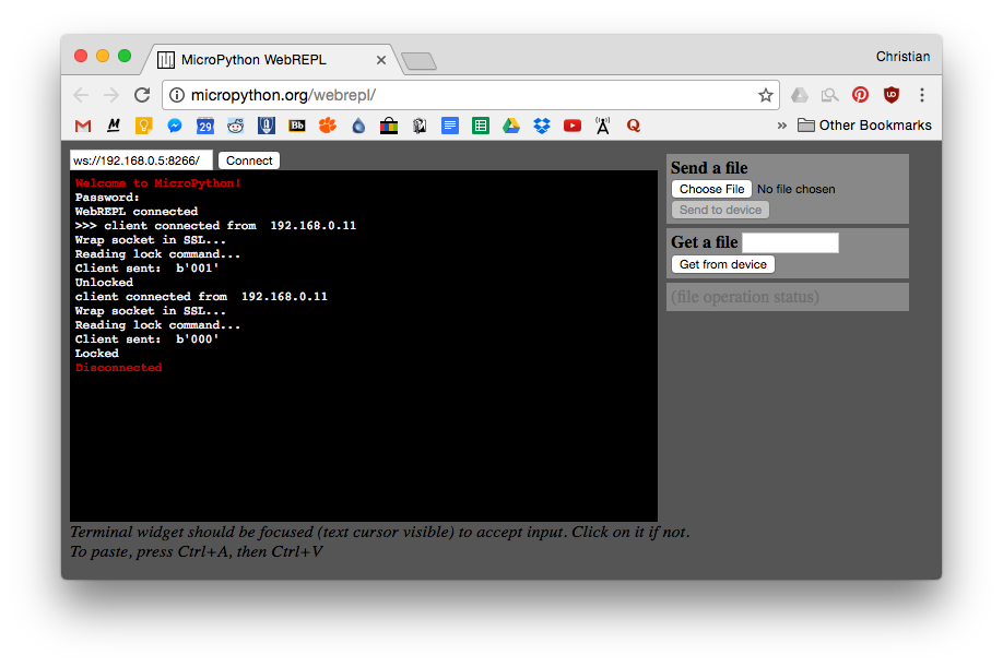
MicroPython, a special port of Python built to run on a number of different embedded devices, offers a few distinct advantages over using the NodeMCU firmware. First, it allows us to utilize the preexisting MircoPython libraries that are quite extensive, and thankfully feature a documented SSL implementation. Second, it would allow for the use of WebREPL so that we could communicate with the device over its WiFi connection. As you can see in image below MicroPython has been nice enough to host a web client interface for WebREPL that allows access to the python prompt as well the ability to send a receive files from the device. This is an extremely useful feature as it allows for the lock mechanism to be updated over WiFi once it has been installed so that new code can be pushed to device without the need for a USB connection.
The process of flashing MicroPython onto the board is fairly straight forward and you can follow the specific details as outlined in the Getting Started section of the MicroPython documentation. You will need to use something called esptool to as well as the latest MicroPython firmware to do so. Once MicroPython is up and running on the ESP8266 it is simply a matter of updating the main.py script along with your own scripts to begin running your own Python scripts on the device.
With MicroPython up and running on the ESP8266 I experimented with first implementing the TCP server as before and with that successfully completed I began to expand the code to include SSL encryption of the stream. This original script can be found on the project GitHub under Microcontroller code directory as server.py. That script was then built upon to allow for a SSL connection between the client and server. The final implementation utilizing TLS/SSL encryption can be found in the same directory as serverSSL.py. In addition to the encryption this server code also features a slightly more sophisticated communication protocol that allows for more robust communication between the client and the server. It can be broken down into two sets of the codes. The first set is made up for three commands that the client is able to send to the server. The client can instruct the device to lock the door, open the door, or request the current lock status. See the table below for the specific details. The next set of the three codes are to be sent by the server to the device to inform the client based on what command it received. It will either inform the client that the door is locked, that the door is open, or that the device has failed to communicate with the lock, indicating there was a hardware failure, and the state of the lock is unknown. While not expressly given a code. a seventh condition exists in which the server receives an invalid command from the client and then sends no response to the client. Therefore the client can consider a closed connection without an acknowledge from the server to have resulted in a corrupted connection with the server and therefore retry the transmission.
100 - server response - the door is locked
101 - server response - the door is opened
111 - server response - hardware error
000 - client command - lock the door
001 - client command - open the door
010 - client command - request status
We can see that all client commands begin with 0 and all server responses begin with 1. Also the locked position refers to a 0 in the least significant bit and similarly a 1 refers to the opened position.
In order to quickly and easily test the communication protocol over the secure SSL connection a built a simple Python script to send the client commands to the server. This script is located in the same directory as the MicroPython scripts and was written to work with Python 2.7.x. It allows the user to either send a lock or open command, or optionally request the current lock status. It should be noted that the server performs the same status check that it does for a request after responding to a client command to lock or open the door as well. This way the client can be sure that their command was accurately read by the server and also performed the desired action.
The server could be better secured with the inclusion of authentication layer on top of the SSL encryption layer. This would only allow authorized users on the network to communicate with the lock mechanism. Although, the current scheme is already somewhat secure due to the use of SSL encryption and the above communication protocol. An unauthorized user would need to have knowledge of the protocol in order to successfully communicate with the lock mechanism. Since encryption is used it would be nearly impossible for the unauthorized users to determine the protocol used so it essentially acts a layer pseudo authentication.
Mobile app
The client application is still currently being developed. One of the other people on my team is currently working on the development using an open source Python framework known as Kivy. This is a cross platform framework that allows for deployment on nearly every platform from Linux, Windows, Android, and iOS. This allows for easy distribution to many platforms without the need to rewrite code.
The mobile app will allow the user to interact with the lock via the established protocol. Therefore it will be able to instruct the lock to change its state as well as request its current state to be shown to the user. Check back here soon to read more details about the final application.
Conclusion
While the mobile app is not yet complete, the rest of the documentation here shows the design and operation of the remote door lock controller. Using the Adafruit Feather HUZZAH as the core of the embedded portion of the system, it was able to use its onboard WiFi capabilities to connect it to any WiFi device for control of the attached electric strike. A TLS/SSL communication system was implemented to ensure that the communication channel was encrypted in an effort to keep the protocol hidden from unauthorized users.
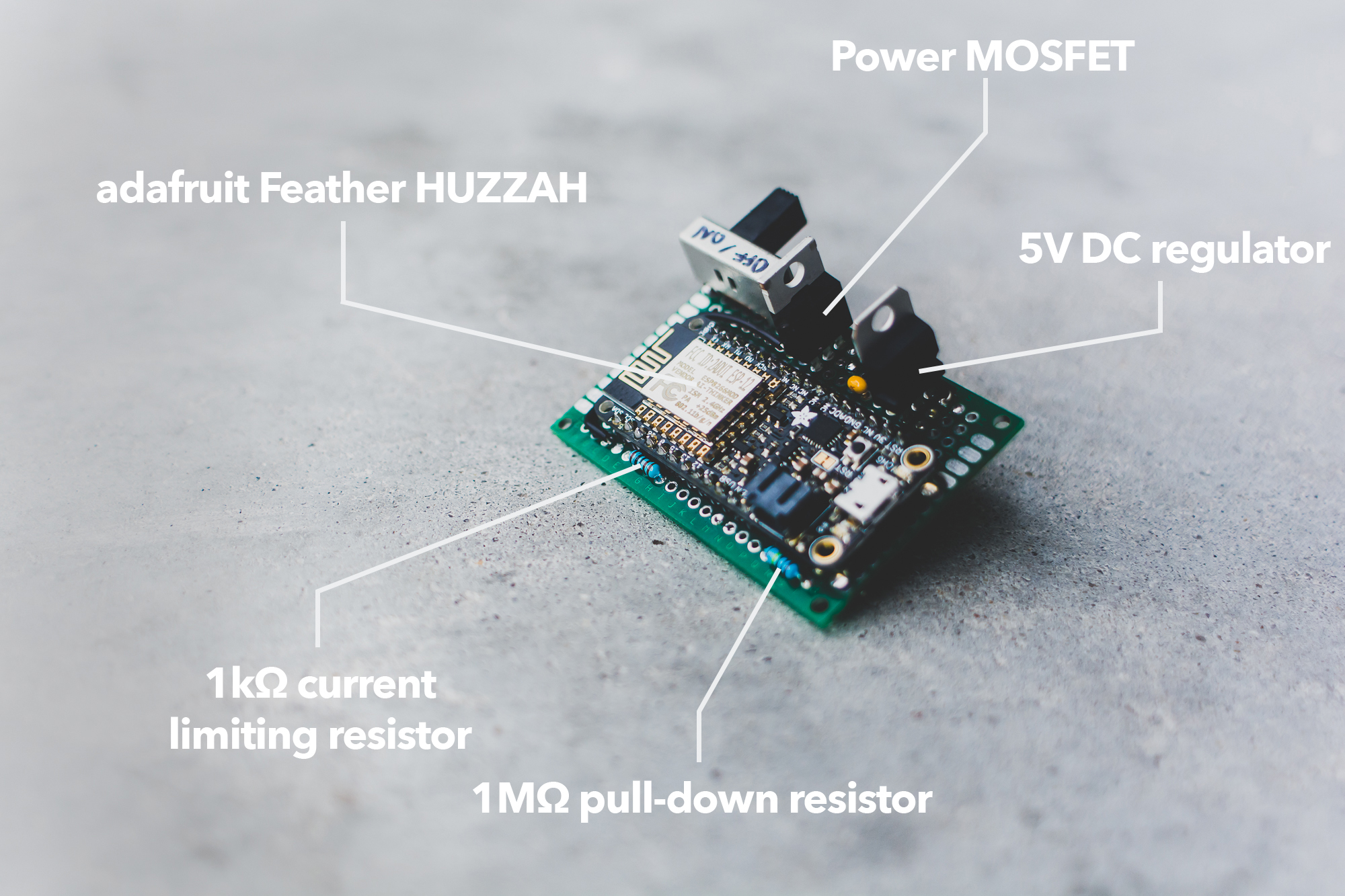
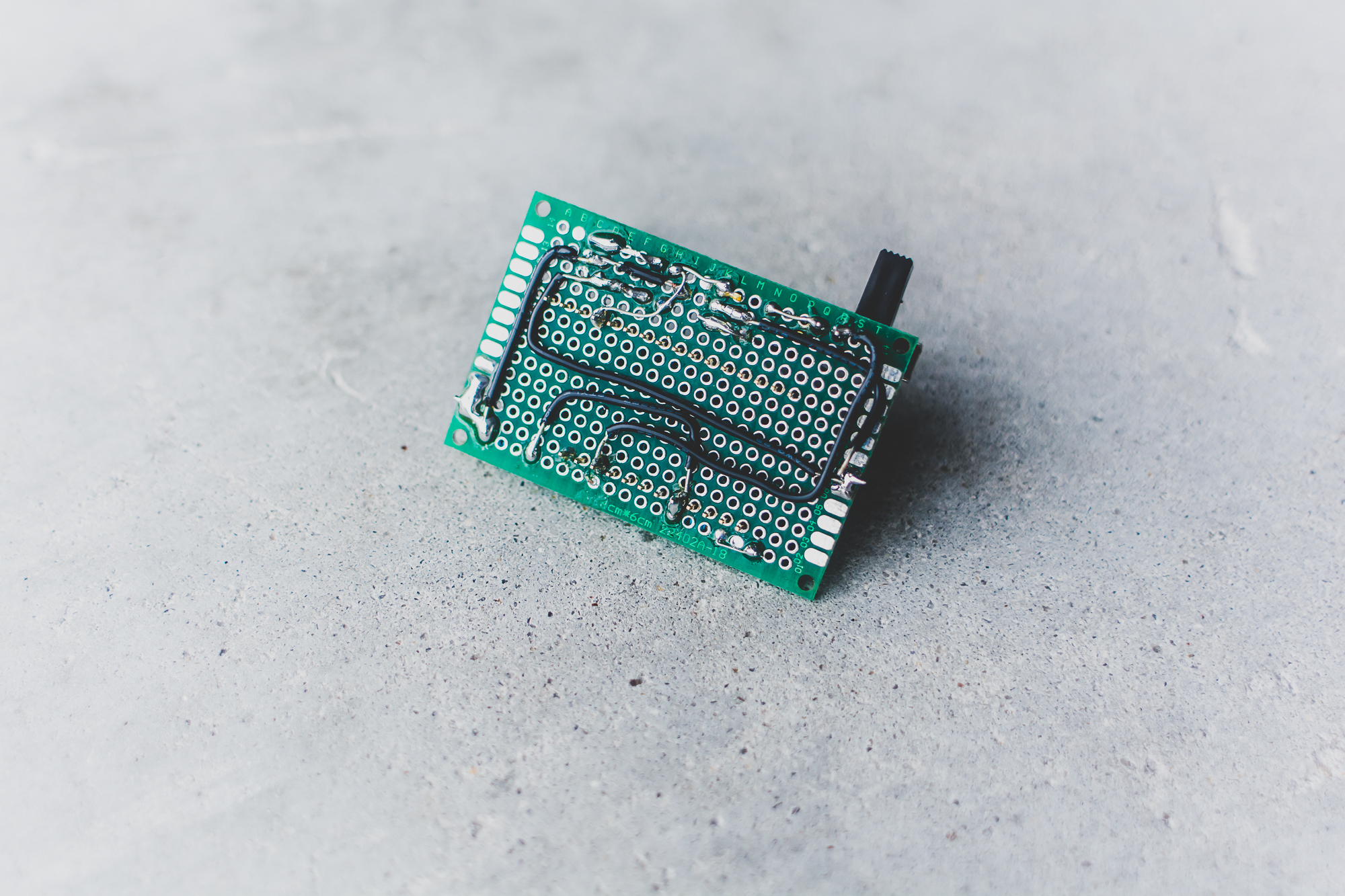
The image below identifies the major hardware components and shows the completed circuitry deployed on a small perfboard. This system could easily be scaled to allow for the implementation of multiple door lock controllers to be controlled by a user from the centralized mobile app.
The biggest ares of improvement for the current system revolve around optimizing the TLS/SSL implementation to decrease the required connection times as well the implantation of an additional authentication layer to ensure that only authorized users have access to the lock controller. Check back in the future to see updates and improvements to the current implementation.