Introduction
This project was completed as part of ECE 4960 - Integrated System Design II. Our team of five was tasked with building a system to play air hockey autonomously. The system needed to meet a number of requirements that included being portable, safe to operate, use the PlayStation Eye for computer vision, and use the Tiva-C Launchpad for motor control.

Our robot, named Clark, in action.
System Overview
We decided to employ a rotary-rotary design, which includes two DC motors in a closed-loop configuration. The computer vision system consists of a PlayStation Eye camera connected to a PC. Frames are analyzed in real-time via a C++ program to detect the puck location, predict future puck trajectories, and leverage this information to provide commands to the Tiva to move the arm, producing high-level gameplay. These commands are sent via UDP to the Tiva. Two proportional controllers implemented in the Tiva are used to supply control signals to the DC motors. Digital encoders provide feedback to the controllers via two LS7366R counter ICs. These controllers generate PWM and direction signals for each DC motor, which are used to operate a dual channel H-bridge motor controller connected to each motor. The complete system is able to dynamically cycle through a number gameplay states that include blocking and volleying a fast moving puck, hitting a slow moving puck, and freeing a puck stuck in the corners of the rink.

Figure 1 Complete system overview
Strengths
Leveraging velocity and trajectory predictions to produce timing and arm positioning for effective blocking.
Dynamic gameplay modes with the ability to block and hit incoming pucks and free stuck pucks.
Adaptive and tunable image processing with parametric gain, exposure, and HSV thresholds via a GUI.
Spacers and 3D printed camera mount for consistent performance with regard to arm and puck positioning.
Weaknesses
Image processing limited to 30 FPS, limiting fastest puck detection.
The puck may drift and become stuck in a few specific locations. The system will not attempt to hit the puck so as to limit hitting the puck into our own goal.
May execute an erroneous motion in relation to the puck movement since it continues operating in certain movement states.
Specific incoming cases will result in powerful and sometimes erratic arm movement.

Figure 2 System block diagram
Mechanical
The arm assembly is composed of two arm sections made of aluminum angles that provide a strong, but lightweight structure. The main DC motor is mounted within the wooden enclosure and features a turntable and an acrylic mount for the main arm. The turntable and a flex-coupler manage off-axis forces between the arm and the main motor. The secondary DC motor is mounted at the end of the main arm and the paddle is secured to the end of this arm with a 3D printed paddle holder as shown in Figure 3.

Figure 3 Rotary-rotary arm assembly with Lazy Susan (turntable)
Electrical
The electrical system is comprised of the Tiva and the dual channel H-bridge. The schematic and wiring diagram for this configuration is shown in Figure 4. The Tiva receives UDP packets that contain the set angles for each of the two motors. These set points are then sent to two separate proportional controllers within the Tiva. These controllers calculate the current angle of the motors by reading the number of counts each motor encoder has undergone over a SPI bus connected to two LS7366R counter ICs. Each controller then outputs a control signal, which is converted to a duty-cycle signal, sent out of the Tiva’s PWM outputs along with GPIO pins that control the direction of each motor. These signals are sent to the dual channel H-bridge that modulates the 12V supply accordingly to move the motors.

Figure 4 Electrical subsystem schematic and wiring diagram
Computer Vision
The computer vision system is comprised of a number of processes that allow for it to effectively track the position of the puck on the playing field. The homography transformation takes the skewed perspective of the camera and translates it to a symmetric, 2-dimensional coordinate plane. GUI sliders allow the user to adjust the HSV thresholds and the camera’s gain and exposure parameters during runtime. With the ability to adjust these parameters at runtime, we can tune the system for various lighting environments and ensure proper detection of the puck. Once the thresholds, gain, and exposure values are finalized, the moment of the binary thresholded image is calculated. This returns the XY coordinates of the centroid of the puck. This information is used to calculate the velocity and puck trajectory using a linear regression on the past four puck locations.
Gameplay Logic
The current location of the puck, the velocity, and the trajectory are used to determine how the arm should be moved, with defending oncoming shots as well as scoring on the opponent being the goal. Figure 5 shows the real-time GUI of the puck detection (pink), trajectory prediction (blue), and the arm path (light blue). We continually check the position and velocity of the puck to determine which of the four main possible states the puck is in. These states consist of the puck being stuck in either a corner, a slow moving puck on our side of the playing field, a puck outside of our side of the playing field, and an oncoming puck. If a corner case is triggered, a special circular path is executed to free the puck. An algorithm we call “follow and hit” is executed for a slow moving puck, which involves following a puck to a position just behind it, and then hitting the puck out of our side of the playing field. If the puck is beyond our reach, the arm will then move to its “home” position, a location centered on the playing field, in front of our goal. The final case is an oncoming puck. For this we use an algorithm called “block and hit”. The trajectory and velocity of the puck are used to determine how to block the puck. Then the arm will move, in a timed fashion, to intercept the puck and immediately hit the puck toward a specified target location (in this case the opponent’s goal).
Award
We won the KEMET Electrical and Computer Engineering Senior Design Award for our project.
Resources
Check out the source code on GitHub
Read our full technical report
And see a video of Clark on YouTube
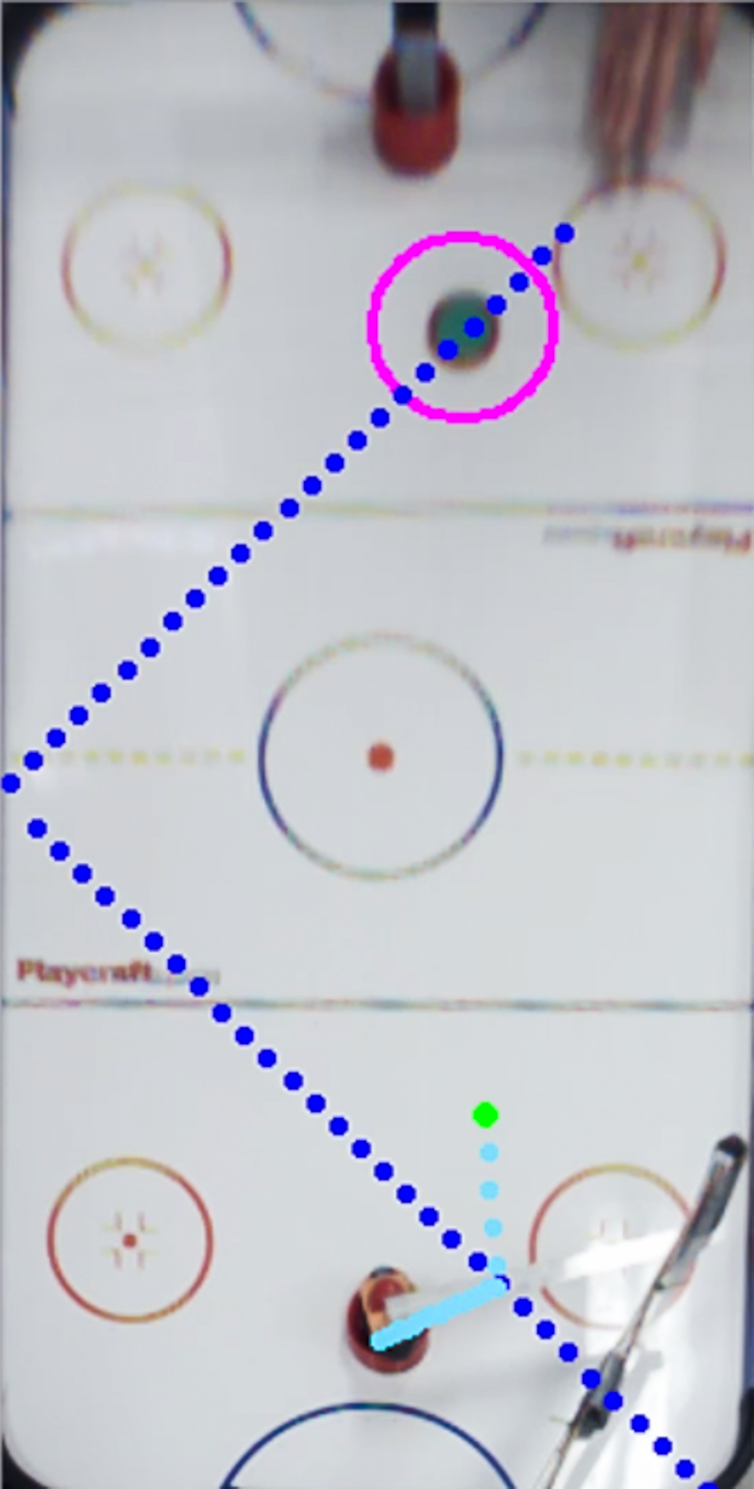
Figure 5 Puck trajectory predictions and arm movements
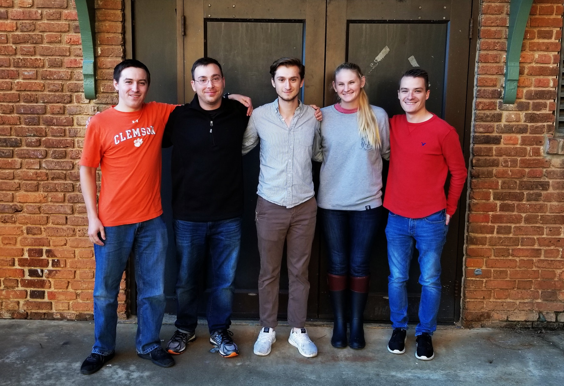
Team AH2 - Edward Bear, Dylan Hastings, Christian Steinmetz, Avery White, and Elexander Fryer